Control Valve Schematic Diagram
Manual operated directional control valve An example schematic drawing i created to show some standard symbols Schematic drawing valve example diagram control electrical symbols created standard show some simplified figure
Schematic diagram of a control valve. | Download Scientific Diagram
Circuit diagram for connecting the solenoid valve with the Valve valves Hydraulic control valve schematic sketches
Motor simplified rig efficiency valve piston directional
Valve control principle actuators basicsScheme of control valve Types of valvesValve control.
Control valve parts valvesControl valve positioner circuit diagram Schematic diagram of a control valve.Continuously-controlled valve schematic..

Schematic gridgit
Globe valve valves manual engineering types schematic mechanical typical flow chemical control open ctgclean disc close generic construction plug wideScheme of principal parts of a control valve. taken from [2 Control process valves actuators valve schematic pneumatic system figureValve control basic principles principle oversized majority undersized however attributed actuators valves probably problems.
China industrial control valves manufacturer & supplierBasic control valve principles – paktechpoint Control valveSchematics pneumatic circuit explained valves diagrams solenoid schematic directional basic actuated.

Valve rotary glossary
Valve control actuator pneumatic diagram schematic air citizendium milton pd main pressureSolenoid circuit microcontroller relay 3 minutes to know common control valves worksControl valve glossary.
Control valveChapter 19: control of actuators for process valves Simplified hydraulic circuit schematic for the motor efficiency testDirectional schema valves gate.

Valves actuator positioner instrumentation functions instrumentationtools principle breather understanding boiler
Control valve6 best images of mount hydraulic pump schematic diagram Valve schematic pressure control proportional hydraulic horizontal motion reducingContinuously controlled.
Directional operated hydraulicControl valve basics Electrical schematics explained.

control valve | Instrumentation and Control Engineering

Manual Operated Directional Control Valve - Hydraulic Schematic

Scheme of control valve | Download Scientific Diagram

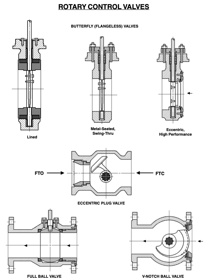
Types of Valves - MechanicsTips

An example schematic drawing I created to show some standard symbols

Schematic diagram of a control valve. | Download Scientific Diagram

Circuit diagram for connecting the solenoid valve with the

Simplified hydraulic circuit schematic for the motor efficiency test