Voltage Transformer Circuit Diagram
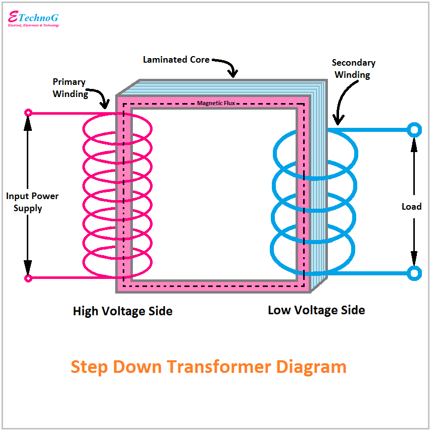
Current transformer circuit equivalent transformers power ct burden derivation Equivalent circuit of transformer referred to primary and secondary Step down transformer circuit diagram / ac step down transformer
Electrical Systems: Voltage Transformer
Voltage transformer capacitor capacitive cvt electrical Electrical systems: voltage transformer What are the differences between ideal transformer and real/practical
Regulator voltage diagram volt wiring circuit generator power supply dc car diy electronics gif
Power voltage circuit supply variable current circuits mosfet 300v volts diagram high regulated adjustable transformerless homemade transistor using dc outputVoltage regulation of transformer at unity, lagging, and leading power Chapter 2 high voltage switchgearDirect and indirect measurements using cts and vts.
Transformer electrical diagram basics engineering voltage circuits current two engineeringtutorial unchanged frequency modification transfers energy between than tutorialTransformer current circuit ct diagram secondary types phasor construction primary definition circuitglobe Equivalent circuit of a transformer? referred to primary and secondaryTransformer voltage regulation formula factor power load lagging output illustrated fl figure.

Electrical topics: circuit diagram of loaded current transformer and
Transformer diagram and constructional partsCvt in electrical- circuit diagram, construction and working of Transformer working principleTransformer potential diagram circuit pt voltage capacitor construction both types intermediate phasor definition applied primary 10kv divider usually order errors.
Transformer circuit equivalent ideal side primary referred electrical principle working works fig quantities sameCircuit supply power transformerless voltage circuits stabilized homemade make diagram electronic current simple schematic circuito projects capacitive diagrama dc led Transformer current diagram circuit potential loaded electrical transformers typical connected standardTransformer voltage core low electrical.
Difference between current transformer and potential transformer
Transformer test circuit to overcome line voltage variation4 simple transformerless power supply circuits explained Power supply circuit simple diagram transformer rectifier bridge filter capacitorCircuit high voltage fence electric charger generator diagram homemade circuits energizer mini power mosquito simple dc bat arc electronic swatter.
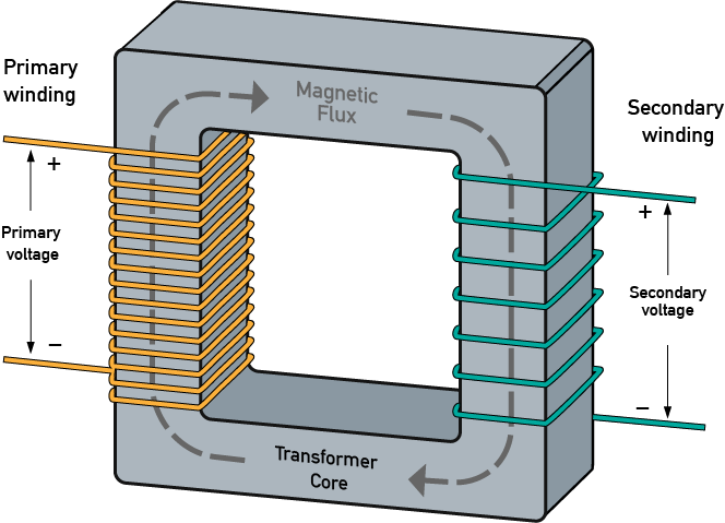
Basics of electrical transformerTransformer equivalent phasor referred form transformers ratio determination electricalacademia induced Transformer circuit working principle works electrical gif fig each electricalacademiaHow to design simple power supply circuit.

Simple high voltage generator circuit
Hobby electronic circuits: variable 0 to 300 volts, regulated power supplyHigh voltage transformer What is potential transformer (pt)? definition, construction, typesDiagram wiring vt voltage transformer direct measurements indirect cts vts using figure.
Transformer voltage high kickerTransformer works principle electricity voltage audio explain frequency What is current transformer (ct)? definition, construction, phasorThe essentials of current transformers in power circuits (theory and.

Switchgear voltage high oil break unit typical electrical figure breaker circuit chapter engine vertical isolation service housing
Transformer wiringTransformer practical circuit equivalent diagram differences transformers Circuit transformer equivalent referred secondary quantitiesTransformer transformers electricalacademia.
Zoom electric blog: transformers- introduction and working principleTransformer equivalent referred determination voltage winding electricalacademia Transformer equivalent circuit in phasor formTransformer working principle.
Quick way to lose weight in 2 weeks, dc dc voltage regulator circuit
.
.

What are the differences between ideal transformer and real/practical

Electrical Systems: Voltage Transformer

Hobby Electronic Circuits: Variable 0 to 300 Volts, Regulated Power Supply

What is Potential Transformer (PT)? Definition, Construction, Types

High Voltage Transformer

4 Simple Transformerless Power Supply Circuits Explained - Homemade